Arduino project best method to control arduino with bluetooth : using app inventor
best method to control arduino with bluetooth
In this tutorial I'll show you How to control Arduino with Bluetooth
using, My app developed with app inventor.
arduino projects 2019-2020
arduino project ideas 2019-2020
arduino projects for kids 2019-2020
arduino project hub 2019-2020
arduino projects book 2019-2020
arduino projects pdf 2019-2020
arduino projects with code 2019-2020
arduino project box 2019-2020
arduino project kits 2019-2020
arduino projector 2019-2020
arduino project book 2019-2020
arduino project handbook 2019-2020
arduino project list 2019-2020
arduino project handbook pdf 2019-2020
arduino project 11 code 2019-2020
arduino project 5 2019-2020
arduino project advanced 2019-2020
arduino project android 2019-2020
arduino project abstract 2019-2020
arduino project alarm clock 2019-2020
arduino project alarm system 2019-2020
arduino project and code 2019-2020
arduino project alarm 2019-2020
arduino project aquarium 2019-2020
arduino project accelerometer 2019-2020
arduino project audio 2019-2020
the arduino project handbook pdf 2019-2020
the arduino projects book pdf 2019-2020
the arduino project handbook 2019-2020
the arduino project 2019-2020
a simple arduino project 2019-2020
arduino with projector 2019-2020
arduino project board 2019-2020
arduino project box lcd 2019-2020
arduino project beginner 2019-2020
arduino project builder 2019-2020
arduino project book code 2019-2020
arduino project box ideas 2019-2020
arduino project book online 2019-2020
arduino project block diagram 2019-2020
arduino project case 2019-2020
arduino project code 2019-2020
arduino project car 2019-2020
arduino project computer controlled rc car 2019-2020
arduino project circuit diagram 2019-2020
arduino project components 2019-2020
arduino project creator 2019-2020
arduino project camera 2019-2020
arduino project cost 2019-2020
arduino project circuit 2019-2020
c arduino projects 2019-2020
arduino projects c code 2019-2020
arduino project designer 2019-2020
arduino project directory 2019-2020
arduino project download 2019-2020
arduino project documentation 2019-2020
arduino project drone 2019-2020
arduino project diagram 2019-2020
arduino project description 2019-2020
arduino project diy 2019-2020
arduino project display 2019-2020
arduino project distance sensor 2019-2020
arduino project examples 2019-2020
arduino project easy 2019-2020
arduino project ebook 2019-2020
arduino project enclosures 2019-2020
arduino project enclosure box 2019-2020
arduino project esp8266 2019-2020
arduino project eclipse 2019-2020
arduino project elevator 2019-2020
arduino project ethernet shield 2019-2020
arduino project encoder 2019-2020
arduino project for beginners 2019-2020
arduino project forums 2019-2020
arduino project for girlfriend 2019-2020
arduino project for car 2019-2020
arduino project for school 2019-2020
arduino project for blind 2019-2020
arduino project for home 2019-2020
arduino project file extension 2019-2020
arduino project for students 2019-2020
arduino project for dummies pdf 2019-2020
arduino project guide 2019-2020
arduino project github 2019-2020
arduino project genius 2019-2020
arduino project guidance 2019-2020
arduino project gps 2019-2020
arduino project guide pdf 2019-2020
arduino project game 2019-2020
arduino project garden 2019-2020
arduino project gsm 2019-2020
arduino project gallery 2019-2020
arduino project handbook vol. 2 pdf 2019-2020
arduino project help 2019-2020
arduino project home automation 2019-2020
arduino project handbook by mark geddes pdf 2019-2020
arduino project handbook volume 2 2019-2020
arduino project handbook vol. 2 2019-2020
arduino project handbook pdf download 2019-2020
arduino project ideas for beginners 2019-2020
In this tutorial I'll show you How to control Arduino with Bluetooth
using, My app developed with app inventor.
Parts Required
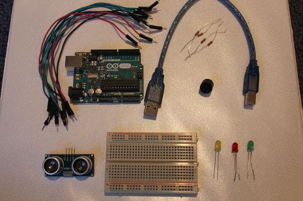
- 1x Arduino
- 1x Bluetooth Module ( HC-06)
- 1x Smartphone (any Android will work)
- 1x Led
- 3x resistors
- 1x Breadboard
- Jumper Cables
Schematics
Arduino Sketch
int ledblue=2;
int tx=1;
int rx=0;
char inSerial[15];
void setup(){
Serial.begin(9600);
pinMode(ledblue, OUTPUT);
pinMode(tx, OUTPUT);
pinMode(rx, INPUT);
allpinslow();
}
void loop(){
int i=0;
int m=0;
delay(500);
if (Serial.available() > 0) {
while (Serial.available() > 0) {
inSerial[i]=Serial.read();
i++;
}
inSerial[i]='\0';
Check_Protocol(inSerial);
}}
void allpinslow()
{
digitalWrite(ledblue, HIGH);
digitalWrite(ledblue, LOW);
}
void Check_Protocol(char inStr[]){
int i=0;
int m=0;
Serial.println(inStr);
if(!strcmp(inStr,"2off")){ //Led Off
allpinslow();
digitalWrite(ledblue, LOW);
Serial.println("Blue Off");
for(m=0;m<11;m++){
inStr[m]=0;}
i=0;}
if(!strcmp(inStr,"2on")){ //Led on
allpinslow();
digitalWrite(ledblue, HIGH);
Serial.println("Blue on");
for(m=0;m<11;m++){
inStr[m]=0;}
i=0;}
else{
for(m=0;m<11;m++){
inStr[m]=0;
}
i=0;
}}
arduino projects 2019-2020
arduino project ideas 2019-2020
arduino projects for kids 2019-2020
arduino project hub 2019-2020
arduino projects book 2019-2020
arduino projects pdf 2019-2020
arduino projects with code 2019-2020
arduino project box 2019-2020
arduino project kits 2019-2020
arduino projector 2019-2020
arduino project book 2019-2020
arduino project handbook 2019-2020
arduino project list 2019-2020
arduino project handbook pdf 2019-2020
arduino project 11 code 2019-2020
arduino project 5 2019-2020
arduino project advanced 2019-2020
arduino project android 2019-2020
arduino project abstract 2019-2020
arduino project alarm clock 2019-2020
arduino project alarm system 2019-2020
arduino project and code 2019-2020
arduino project alarm 2019-2020
arduino project aquarium 2019-2020
arduino project accelerometer 2019-2020
arduino project audio 2019-2020
the arduino project handbook pdf 2019-2020
the arduino projects book pdf 2019-2020
the arduino project handbook 2019-2020
the arduino project 2019-2020
a simple arduino project 2019-2020
arduino with projector 2019-2020
arduino project board 2019-2020
arduino project box lcd 2019-2020
arduino project beginner 2019-2020
arduino project builder 2019-2020
arduino project book code 2019-2020
arduino project box ideas 2019-2020
arduino project book online 2019-2020
arduino project block diagram 2019-2020
arduino project case 2019-2020
arduino project code 2019-2020
arduino project car 2019-2020
arduino project computer controlled rc car 2019-2020
arduino project circuit diagram 2019-2020
arduino project components 2019-2020
arduino project creator 2019-2020
arduino project camera 2019-2020
arduino project cost 2019-2020
arduino project circuit 2019-2020
c arduino projects 2019-2020
arduino projects c code 2019-2020
arduino project designer 2019-2020
arduino project directory 2019-2020
arduino project download 2019-2020
arduino project documentation 2019-2020
arduino project drone 2019-2020
arduino project diagram 2019-2020
arduino project description 2019-2020
arduino project diy 2019-2020
arduino project display 2019-2020
arduino project distance sensor 2019-2020
arduino project examples 2019-2020
arduino project easy 2019-2020
arduino project ebook 2019-2020
arduino project enclosures 2019-2020
arduino project enclosure box 2019-2020
arduino project esp8266 2019-2020
arduino project eclipse 2019-2020
arduino project elevator 2019-2020
arduino project ethernet shield 2019-2020
arduino project encoder 2019-2020
arduino project for beginners 2019-2020
arduino project forums 2019-2020
arduino project for girlfriend 2019-2020
arduino project for car 2019-2020
arduino project for school 2019-2020
arduino project for blind 2019-2020
arduino project for home 2019-2020
arduino project file extension 2019-2020
arduino project for students 2019-2020
arduino project for dummies pdf 2019-2020
arduino project guide 2019-2020
arduino project github 2019-2020
arduino project genius 2019-2020
arduino project guidance 2019-2020
arduino project gps 2019-2020
arduino project guide pdf 2019-2020
arduino project game 2019-2020
arduino project garden 2019-2020
arduino project gsm 2019-2020
arduino project gallery 2019-2020
arduino project handbook vol. 2 pdf 2019-2020
arduino project help 2019-2020
arduino project home automation 2019-2020
arduino project handbook by mark geddes pdf 2019-2020
arduino project handbook volume 2 2019-2020
arduino project handbook vol. 2 2019-2020
arduino project handbook pdf download 2019-2020
arduino project ideas for beginners 2019-2020


